

Our day-to-day work mainly involves assessing geological and engineering conditions, hydrogeological conditions, identifying adverse processes and phenomena, and estimating the physical and mechanical properties of soil and rock for the purposes of construction, spatial planning and the development of underground space.
A large part of our work involves projects in which we use geophysical surveys to identify or refine the geological structure, for example, for the preparation of Detailed Geological Maps of Poland at a scale of 1:50,000, Detailed Geological Maps of the Sudetes at a scale of 1:25,000, or the Detailed Geological Maps of the Świętokrzyskie Region at a scale of 1:25,000. We carry out work related to the exploration of shallow deposits.
We are also involved in the implementation of new measurement techniques through conceptual work and research projects.
We are the authors of several manuals, guidelines, monographs and articles, in which we aim to describe, in a practical manner, the possible applications of engineering geophysics methods.
ENGINEERING GEOPHYSICS
Engineering geophysics deals with the practical application of geophysical surveys to characterise geological structures. Engineering geophysical methods are used to investigate the rock mass over a very wide depth range, from the surface to several tens of kilometres below. It is important not to equate engineering geophysics solely with depth, for example with shallow geophysical surveys such as MASW (surface wave analysis) with a limited depth range, but rather with its purpose, namely the assessment of rock mass for engineering purposes other than the oil industry or the investigation of deep subsurface structures unrelated to the mapping of mineral deposits.
Methods for mapping geological structures using engineering geophysics have been adapted to address engineering challenges relating to construction, urbanisation and the energy transition in the broadest sense, regardless of depth.
GEOPHYSICAL SURVEY METHODS
Textbooks and review articles in the field of geophysics present a variety of classifications and categorisations of geophysics. These categorisations reflect the authors’ different approaches, which depend on the subject scope of the publication.
We have developed our own classification of geophysical methods (within the field of engineering geophysics), which we have based on the nature of the physical fields being measured and the physical properties of the soil and rock medium. This classification has been adapted to the issues most frequently encountered in engineering geology; consequently, engineering geophysical methods have been divided into five main groups:
- Electrical resistivity methods (GR-I), which determine the electrical resistivity of the subsurface using direct current. This group also includes induced polarization (IP) surveys, as these are always performed in conjunction with electrical resistivity surveys (e.g. VES, ERT).
- Electromagnetic methods (GR-II), which determine the electrical resistivity (or conductivity) of the subsurface using alternating electromagnetic fields.
- Ground-penetrating radar methods (GR-III), which use the reflection of electromagnetic waves to determine the relative electrical permittivity of subsurface layers, enabling the identification of layer boundaries.
- Seismic methods (GR-IV), which use measurements of seismic-wave velocities to determine the position of boundaries between soil and rock layers and to estimate the elastic parameters of the soil - rock medium.
- Potential field methods (GR-V), in which, depending on the type of potential field, the following are determined:
-based on the total magnetic field intensity, the presence of ferromagnetic bodies is identified - magnetic methods (magnetometry);
- based on gravity measurements, changes in the mass distribution within the soil - rock medium (mass-distribution anomalies) are determined - gravity methods (gravimetry).
And this is what it looks like in the infographic:
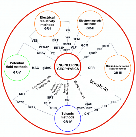
In the table below, we have listed the names and abbreviations for the various methods used in engineering geophysics.
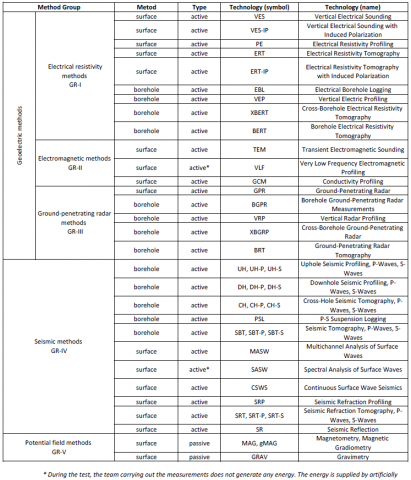
Geoelectric methods - electrical resistivity (Group I)
SURFACE METHODS
-
VES - Vertical Electrical Sounding, allowing analysis of the vertical distribution of electrical resistivity.
-
VES - IP - Vertical Electrical Sounding with Induced Polarization.
-
PE - Electrical Resistivity Profiling, used to investigate the horizontal distribution of electrical resistivity.
-
ERT - Electrical Resistivity Tomography, enabling detailed 2D or 3D imaging of the subsurface.
-
ERT- IP - Electrical Resistivity Tomography with Induced Polarization, used for more advanced geological and geotechnical analyses.
Measurement technique, application and interpretation
The depth of investigation in surface electrical resistivity methods is related to the length of the electrode array. The maximum investigation depth is typically approximately 20 - 25% of the distance between the outermost current electrodes. Interpretation accuracy decreases with increasing depth, which limits the applicability of these methods for very deep investigations.
The results are interpreted based on geoelectrical sections, which show zones characterized by different electrical resistivity values. These zones are subsequently correlated with specific geological objects, such as rock layers, or geotechnical features, such as weakened or fractured zones.
Limitations
Electrical resistivity methods are relatively resistant to interference compared with other geophysical methods; however, they are not completely free from disturbances. Interference may occur between the measuring equipment and electromagnetic fields generated by power lines or industrial equipment. In addition, the presence of conductive anthropogenic elements, such as metal pipes or uninsulated cables, may introduce significant errors into the interpretation of the data.
BOREHOLE METHODS
-
EBL - Electrical Borehole Logging
-
VEP - Vertical Electrical Profiling
-
XBERT - Cross-Borehole Electrical Resistivity Tomography, including measurements between two boreholes.
-
BERT - Borehole Electrical Resistivity Tomography, allowing a 2D or 3D image to be obtained for the area between boreholes.
Measurement technique, application and interpretation
Electrical resistivity tomography measurements are performed between boreholes or between a borehole and the ground surface. A pair of current electrodes generates an electrical current, creating an electric field in the subsurface. The remaining electrodes record changes in voltage and current within the electric field, enabling reconstruction of the distribution of electrical resistivity.
When the results can be calibrated against lithological profiles from boreholes, the method allows precise determination of the distribution of geological bodies, such as layers, ore bodies, or fracture zones, within the plane between the boreholes.
Limitations
Borehole investigations require specific technical conditions concerning borehole construction. Casing pipes cannot be made of conductive materials, such as metal, in order to avoid short circuits; at the same time, they must not electrically isolate the borehole from the surrounding rock mass. Consequently, such measurements can generally be performed only in uncased boreholes, which limits their application in loose sediments and certain other types of non-rock subsurface materials.
Geoelectric methods - electrical resistivity (Group II)
SURFACE METHODS
-
TEM - Transient Electromagnetic Sounding, enabling measurements of changes in the electromagnetic field as a function of time.
-
VLF - Very Low Frequency Electromagnetic Profiling, mainly used to investigate deeper geological structures.
-
GCM - Conductivity Profiling, used for shallow investigation of subsurface conditions.
Measurement technique, application and interpretation
The TEM method is a point-based technique, similar to electrical resistivity sounding, allowing detailed investigation of subsurface conditions at selected locations. It is characterized by a considerable depth of investigation and can identify geological structures extending to depths of several hundred metres. At the same time, the method is highly sensitive to electromagnetic interference, both natural and anthropogenic, which requires measurements to be conducted in an environment with as little electromagnetic noise as possible.
Conductivity Profiling (GCM) measurements are typically carried out along predefined survey lines using a specified measurement interval. The measurement spacing is often very dense, sometimes less than 1 m, allowing detailed mapping of the spatial variability of geophysical parameters.
Electromagnetic methods, such as GCM and TEM, can provide valuable complementary information to electrical resistivity methods (ERT), particularly in the development of geological models. Conductivity Profiling (GCM) enables rapid investigation of the shallow subsurface, typically to depths of several metres, making it useful for preliminary mapping of lithological variability over large areas. In contrast, TEM allows investigations at considerably greater depths than ERT, reaching several hundred metres, and can therefore be used to analyse larger-scale subsurface structures. When developing a comprehensive geological model, different combinations of these methods can be applied to obtain both detailed information on shallow layers and information on deeper structures, providing a more complete and reliable characterization of the subsurface.
Limitations
A major limitation of electromagnetic methods is the presence of metallic anthropogenic objects in the ground and on the ground surface. Objects such as pipes, cables, and other conductive elements can interfere with measurements and introduce significant errors in interpretation. Therefore, the accuracy of surveys conducted in urbanized areas or in locations affected by intense anthropogenic electromagnetic interference may be considerably reduced.
Geoelectric methods - electrical resistivity (Group III)
Based on the reflection of the electromagnetic wave, the relative electrical permittivity of the layers can be determined, allowing their boundaries to be identified.
SURFACE METHODS
- GPR - Ground-Penetrating Radar
Measurement technique, application and interpretation
In ground-penetrating radar surveys of the subsurface, antennas operating in the frequency range of approximately 100 - 500 MHz are most commonly used. The frequency is selected according to the required depth of investigation and horizontal and vertical resolution. The measurement interval is adjusted to the required horizontal imaging accuracy and is typically from several to several dozen centimetres. Under favourable ground conditions, such as a dry and uncontaminated environment, the maximum investigation depth is generally several metres.
GPR surveys provide information on the boundaries between layers characterized by different values of relative electrical permittivity, as well as the location of objects with high electrical conductivity or strong electromagnetic response, such as metal cables and pipes. However, the method does not provide direct information on other physical properties, such as mineral composition or moisture content.
The most common applications of GPR include:
- detection of underground infrastructure, such as pipes, cables, and foundations;
- identification of lithological boundaries, such as the base of embankments or sedimentary layering;
- identification of fracture zones, voids, and other anomalies within soil or rock formations.
Limitations
The main limitation of GPR is electromagnetic attenuation and shielding, which occurs particularly in materials with low electrical resistivity. This applies to both natural environments, such as clayey or saline-water-bearing soils, and anthropogenic materials, such as heavily reinforced concrete. Such materials can strongly attenuate or even prevent the penetration of electromagnetic waves, reducing the investigation depth to as little as a few centimetres.
In addition, the strong influence of metallic objects in the subsurface can cause distortions in the recorded data and reduce the effectiveness of GPR surveys in urbanized areas.
BOREHOLE METHODS
-
BGPR - Borehole Ground-Penetrating Radar Measurements, used for detailed investigation of subsurface conditions in boreholes.
-
VRP - Vertical Radar Profiling, allowing determination of the electrical permittivity of layers along the borehole axis.
-
XBGPR - Cross-Borehole Ground-Penetrating Radar Measurements, enabling imaging of zones between two or more boreholes.
-
BRT - Ground-Penetrating Radar Tomography, used to obtain detailed 2D and 3D sections of the area between boreholes.
Measurement technique, application and interpretation
Borehole GPR surveys require specialized antennas that can be inserted into boreholes. This technology enables imaging of fracture zones, voids, and other discontinuities in the subsurface, particularly in competent rock formations. These methods are mainly used for:
characterization of fracture zones and voids in competent rocks;identification of underground cavities and channels;detailed investigation of structures within rock masses.
Limitations
The application of borehole GPR methods is largely limited to competent rock formations. The methods require uncased boreholes, as the presence of metal casing prevents electromagnetic waves from penetrating the surrounding formation and can make measurements impossible.
These limitations mean that borehole GPR methods are rarely applied in unconsolidated soils or in areas characterized by a high level of anthropogenic electromagnetic interference.
Seismic methods (Group IV)
Seismic methods use measurements of seismic wave velocities to determine the position of boundaries between soil and rock layers and to estimate the elastic properties of the subsurface. They are an essential tool in geotechnical and geological investigations, enabling detailed analysis of the mechanical properties of the subsurface.
SURFACE METHODS
-
MASW - Multichannel Analysis of Surface Waves
-
SASW - Spectral Analysis of Surface Waves
-
CSWS - Continuous Surface Wave Seismic, providing 1D results
-
SRP - Seismic Refraction Profiling
-
SRT, SRT-P, SRT-S - Seismic Refraction Tomography, for P- and S-waves
-
SR - Seismic Reflection
Measurement technique, application and interpretation
Seismic surveys use multichannel seismographs, typically with at least 24 channels. The equipment records the amplitude of ground vibrations as a function of time for a series of sensors, such as geophones or hydrophones, distributed along the survey line. The measurement interval, typically between 1 and 5 m, is selected according to the required horizontal resolution.
Seismic methods are particularly effective for determining the mechanical parameters of the subsurface, such as deformation and stiffness moduli. Based on the analysis of seismic wave velocities, it is possible to identify zones of loosened soil, boundaries of low-bearing-capacity soils, and zones of structural damage in rock masses, such as slip surfaces in landslides.
Limitations
Seismic methods are sensitive to external disturbances, particularly low-frequency acoustic waves (below approximately 100-200 Hz). Such disturbances may originate from anthropogenic sources, including road traffic and industrial machinery, or from natural sources, such as wind, rainfall, and ground vibrations. In some cases, surveys may need to be conducted during nighttime hours to minimize the influence of such disturbances.
In addition, geophones used in seismic surveys may be affected by electromagnetic interference, particularly in the vicinity of poorly shielded power lines.
BOREHOLE METHODS
-
UH, UH-P, UH-S - Uphole Seismic Profiling, for P- and S-waves
-
DH, DH-P, DH-S - Downhole Seismic Profiling, for P- and S-waves
-
CH, CH-P, CH-S - Cross-Hole Seismic Tomography, for P- and S-waves
-
PSL - P-S Suspension Logging
-
SBT, SBT-P, SBT-S - Seismic Tomography, for P- and S-waves
-
Cross-hole seismic measurements
Cross-hole seismic measurements determine the velocity of seismic waves through the subsurface between two boreholes located at the same depth. A seismic source is placed in one borehole and a receiver, typically a multicomponent geophone, in the other. Based on the measured travel distance and travel time of the seismic wave, the average seismic wave velocity can be determined, allowing detailed characterization of the mechanical properties of the subsurface.
Seismic tomography
Seismic tomography is an extension of cross-hole seismic measurements that enables 2D and 3D imaging of the investigated volume. Seismic sources and receivers are distributed at multiple depths and at relatively close intervals, allowing numerous seismic ray paths, including crossing ray paths, to be recorded.
Numerical analysis of the recorded data enables detailed reconstruction of the spatial distribution of seismic wave velocities, most commonly P-wave velocities. This approach is particularly useful for investigating engineering structures and their surroundings, such as tunnels, excavations, and walls.
Uphole and downhole seismic profiling
These methods are used to determine the vertical distribution of seismic wave velocities. In the up-hole configuration, the seismic source is located at the ground surface, while the receivers are positioned in the borehole. In the down-hole method, the configuration is reversed, with the source located in the borehole and the receivers at the surface.
The results allow profiles of P- and S-wave velocities to be established for different depths, providing a detailed assessment of the mechanical properties of the subsurface.
Limitations
As with surface seismic methods, borehole seismic surveys are sensitive to acoustic and electromagnetic interference. In addition, they require precisely constructed boreholes that must be appropriately positioned and accurately correlated with one another.
In the case of cross-hole seismic measurements, the homogeneity and continuity of the subsurface between the boreholes are important factors affecting the reliability of the results. Significant lateral changes in lithology or seismic properties between the boreholes may complicate interpretation and reduce the accuracy of the calculated parameters.
Potential field methods (Group V)
Potential field methods use measurements of potential fields to investigate geological conditions and anomalies within the soil and rock subsurface. Depending on the type of field measured, the following methods can be distinguished:
- Magnetometric methods - based on measurements of the total magnetic field intensity. They are used to identify bodies with ferromagnetic properties, such as magnetic rocks or anthropogenic metallic objects.
- Gravimetric methods - based on measurements of the gravitational field intensity. They are used to identify variations in the distribution of mass within the subsurface, enabling the detection of anomalies such as voids, caves, loosened zones, and mining damage.
SURFACE METHODS
- MAG, gMAG – Magnetometry, including gradient magnetometry
- GRAV – Gravimetry
Measurement technique, application and interpretation
Magnetometry: Magnetometric surveys allow rapid and effective detection of ferromagnetic objects, such as metal structures and rocks rich in magnetic minerals. The method is particularly useful for locating old foundations, wrecks, metal tanks, as well as for archaeological and military investigations. The spacing of measurement points depends on the required resolution and typically ranges from several centimetres to several metres.
Gravimetry: Gravimetric surveys, particularly microgravity surveys, use measurement intervals of the order of a few metres, enabling the detection of small gravitational anomalies. The method can be applied to:
- locating voids, such as caves and zones affected by suffosion;
- identifying zones of loosened soil, e.g. associated with mining damage or landslides;
- detecting old adits and underground workings.
Interpretation of the results is based on the analysis of the spatial distribution of magnetic or gravitational anomalies, which are subsequently correlated with specific geological features or anthropogenic structures.
Limitations
Magnetometry: Magnetometric surveys can be significantly affected by the presence of metallic objects on the ground surface, such as fences, pipes, and other anthropogenic structures. The method is also less effective where magnetic objects are located at considerable depths or are surrounded by materials with weak magnetic properties.
Gravimetry: Gravimetric surveys are highly sensitive to vibrations, which can make measurements difficult near roads, industrial facilities, or areas subject to significant mechanical activity. In addition, the method requires a sufficiently large density contrast between the investigated objects and the surrounding subsurface. In soils with a relatively homogeneous structure and natural continuity, gravimetry may not provide satisfactory results, making its application under such conditions of limited justification.
THE USEFULNESS OF GEOPHYSICAL SURVEYS
Determining the appropriate research methods for specific engineering geology problems is challenging, mainly due to the difficulty of establishing a comprehensive catalogue of problems and issues that may be encountered in engineering practice. The diversity of geological conditions, research objectives, and technical and economic constraints means that method selection requires an individual approach.
The experience of the person conducting the investigation and preparing the documentation, as well as the availability of different geophysical methods, may also be crucial. Methods should be selected so that the distribution of the measured physical fields represents the investigated structures and geological formations as accurately and unambiguously as possible.
Application of multiple geophysical methods
The use of several geophysical methods based on different physical principles is recommended, as this allows the results to complement each other and reduces interpretation uncertainty. For example, in investigations of flysch formations, the application of the electrical resistivity method can provide information on lithology, whereas seismic methods can be used to assess the degree of tectonic deformation. Similarly, when determining the morphology of the top of the bedrock beneath Quaternary sediments at depths of several to several dozen metres, combining different methods can provide more reliable results.
In general, it can be assumed that most investigation objectives can be achieved when there is sufficient contrast in the parameters measured within the investigated medium. In other words, if two layers consist of sediments with similar resistivity values, such as clay overlying marls, or have similar seismic velocities, it may be difficult to determine the boundary between them.
Another important factor is the resolution of the methods. A fundamental principle should be kept in mind: the resolution of the method must be sufficiently high to identify the thickness of the layer or the size of the object being investigated. It should also be noted that the resolution of every geophysical method generally decreases with increasing depth.
Limitations of geophysical methods
Although the use of several methods in geophysical investigations allows more comprehensive data to be obtained, in industrial practice the selection of methods is often constrained by the cost and duration of the investigation. For example, in gravimetric and magnetometric surveys, the effects resulting from variations in the subsurface may be small, while the cost of the investigation may be relatively high. In such situations, particularly where the gravitational or magnetic response generated by subsurface variability is negligible, the application of these methods may be economically unjustified.
Example: Investigation of subsurface voids
For an investigation aimed at determining the location and extent of subsurface voids, gravimetry may theoretically be an effective method. Voids within rock formations can generate a negative gravity anomaly, which can be used to identify their location and estimate their geometry.
However, reliable investigation requires a very dense measurement grid covering an area larger than the diameter of the void, which significantly increases the cost and duration of the survey. In addition, vibrations caused by anthropogenic activities, such as road traffic or construction works, may interfere with measurements and prevent sufficiently accurate results from being obtained.
In emergency situations, such as when voids are discovered during construction works, it may be impractical to suspend the works for the time required to carry out a detailed gravimetric survey. In such cases, methods that are less sensitive to anthropogenic interference may be more appropriate.
It should also be noted that seismic waves and electric field lines do not propagate directly through voids. The geological model representing the actual subsurface structures is generated only during the processing and interpretation of the acquired data.
The following section presents several important limitations associated with individual methods used in engineering geophysics. This is not intended to be an exhaustive list, and the presence of a given limitation does not necessarily exclude the use of a particular method. In specific circumstances, for example, ERT measurements can be carried out across a concrete-paved area by drilling through the hard surface and installing the electrodes. The purpose of the comparison is therefore to indicate factors that may significantly hinder fieldwork or interfere with the measurements.
Below are some important limitations for each of the engineering geophysics survey methods. This is not an exhaustive list, nor does a particular limitation rule out the use of a given method, as in specific cases it is possible, for example, to carry out ERT measurements on a concrete-paved site (e.g. by drilling through the hard surface and driving in electrodes); however, the purpose of this summary is to highlight what may, in fact, significantly complicate fieldwork or interfere with measurements.
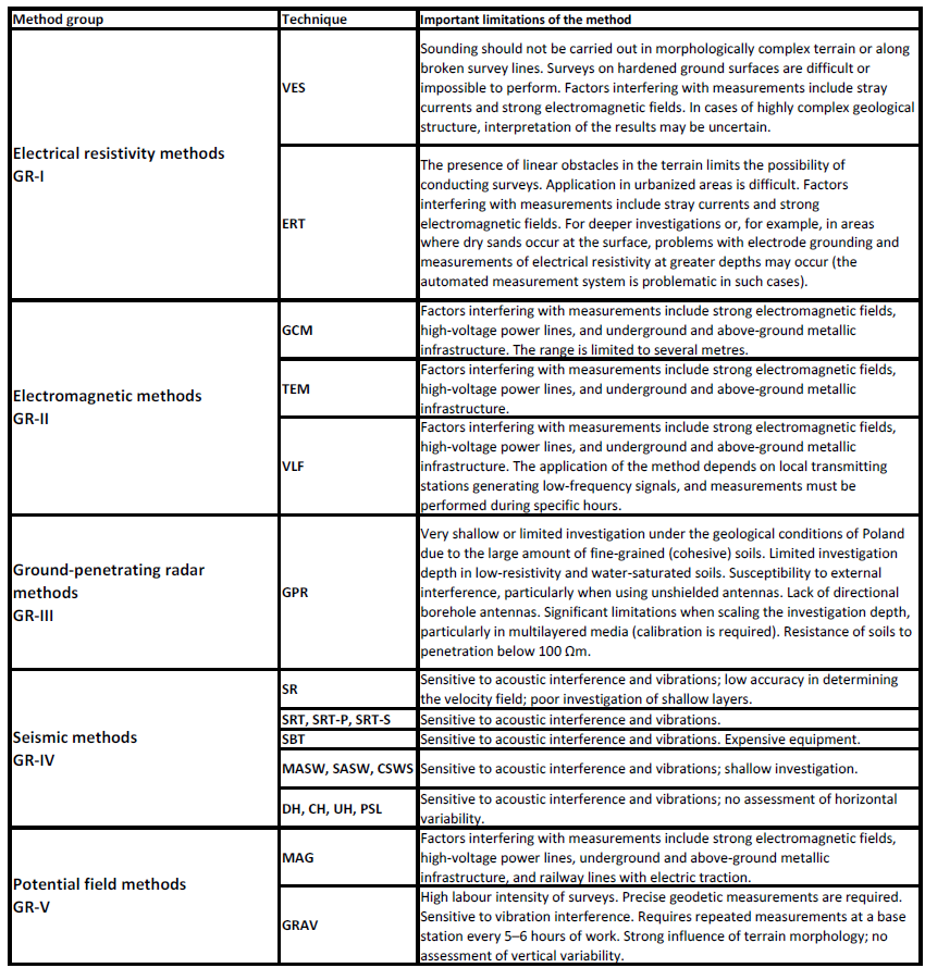
Two very important aspects of geophysical investigations should be highlighted, as they are often overlooked and insufficient attention is paid to them.
The first concerns conducting geophysical surveys in areas where the natural geological setting has been disturbed. This includes both changes in geological structure, such as anthropogenic soils or unnatural objects occurring within the investigated geological space, and soil contamination, water mineralization, interference from above-ground and underground infrastructure, areas affected by strong electromagnetic fields, traffic, and other sources of disturbance. In such areas, a large proportion of the results obtained from geophysical investigations may be unreliable. The results may be difficult to interpret correctly and may be associated with significant uncertainty. In general, the space described above should be considered highly unfavourable for the application of geophysical methods.
The second aspect concerns conducting geophysical investigations in areas with variable terrain morphology, which is often accompanied by significant variability in geological structure. Geophysical measurements are performed in three-dimensional space, whereas their standard processing and subsequent visualization are usually carried out in 2D (or 1D). The results presented in sections are therefore two-dimensional. The spatial aspect of the geological structure is often overlooked. This is frequently reflected in a tendency to interpret the survey results within a vertical plane perpendicular to the ground surface along the survey line. This can be a source of significant interpretation errors.
A particular example is provided by survey results where geophysical sections intersect and the interpreter expects the measurement results to be identical at the point of intersection. When a three-dimensional space with significant spatial variability is considered, the results at the intersection may, in fact, differ.
Depth of investigation and resolution
The application of geophysical methods in engineering geophysics is associated with two important aspects:
- depth of investigation;
- method resolution.
Spatial resolution and measurement resolution decrease with increasing depth of investigation of the soil and rock medium. Consequently, different geophysical methods are applicable to different depth ranges, while the resulting geological interpretation or parameterization of the subsurface may vary in accuracy and be associated with different levels of uncertainty.
It should also be noted that, for many construction or underground spatial-development purposes, the geological model becomes increasingly generalized with depth. Therefore, the application of methods providing very high accuracy and resolution is not always necessary.
The issues of resolution and depth of investigation are considered differently for active and passive methods. It is difficult to define fixed depth ranges within which a particular method can be applied. The depth of investigation, required horizontal and vertical resolution, and the objective of the survey should determine which methods are appropriate for solving a given geological and engineering problem.
When planning geophysical investigations, the general principle is that the greater the required depth of investigation, the lower the spatial density of measurements. Accordingly, the following depth classification is proposed for engineering geophysics:
- shallow investigations - investigation depths of up to 5 m below ground level (b.g.l.);
- medium-depth investigations - investigation depths of 5-30 m b.g.l.;
- deep investigations - investigation depths of 30-50 m b.g.l.;
- very deep investigations - investigation depths of >50 m b.g.l.
The table below presents the engineering geophysics methods applicable to the proposed depth ranges.
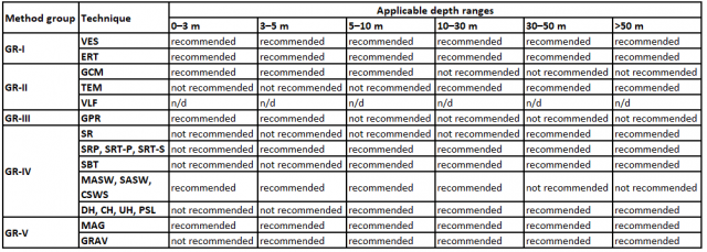
Engineering geophysical investigation methods can be divided into universal methods, which can be applied across the full range of investigation depths, and methods with limitations, which cannot be used effectively across the entire depth range. In many cases, the choice of method is determined by the time and cost of the investigation. For example, when investigating an area at high resolution for archaeological purposes, where the required investigation depth is only 1-2 m, Conductivity Profiling (GCM) may be more appropriate than Electrical Resistivity Tomography (ERT). The depth ranges for engineering geophysical methods presented in the table above were developed based on published literature and the authors’ many years of experience in conducting geophysical investigations.
In geophysical investigations for engineering purposes, as in any other field of applied research, the economic factor must also be taken into account. Geophysical surveys should be designed to achieve the highest possible ratio of investigation effectiveness to cost. Those designing the investigation must determine the required investigation depth and resolution, as well as identify which investigations would be excessive in relation to the objectives. Survey contractors also work with measurement equipment - particularly for active methods - that is designed for typical engineering geology applications. Such equipment may be capable of recording signals from a limited number of receivers, while the accessories used, typically signal cables, impose limits on the maximum separation between sensors. The flexibility of the measurement procedure is therefore usually limited, and increasing this flexibility may involve a substantial increase in costs.
Consequently, the planning of geophysical investigations requires close cooperation between the client, whose role is to clearly define the problem to be solved, and the person designing the investigation, who should have appropriate experience in engineering geophysical surveys.
As a practical approximation of the relationship between investigation depth and resolution, the following principles can be adopted:
- the depth of investigation is proportional to the length of the measurement array used;
- the depth of investigation is proportional to the power of the applied source; the depth of investigation is inversely proportional to the frequency of the waves used in the investigation;
- the investigation resolution is inversely proportional to the spacing between the elements of the measurement array;
- the investigation resolution is proportional to the frequency of the waves used in the investigation;
- the resolution of geophysical investigations decreases with increasing depth.